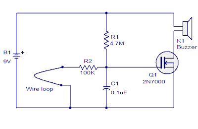
 Here is the circuit diagram of the loop wire alarm based on a simple improved N-channel FET 2N700, a bell and the normal condition of some components.In passive door 2N700 (Q1) is connected to the ground through a 100K resistor (R2) and the wire loop. When the wire loop is broken, Q1 will be biased to the active state and tone is a very activated.The circuit consumes less current STANDBY and the battery will last a very long period of time.
Circuit and Wiring Diagram for Automotive, Car, Motorcycle, Truck, Audio, Radio, Electronic Devices, Home and House Appliances
Search Other Blog
Browse » Home »
Lock and Alarm
» Wire Loop Alarm based on 2N700
Wire Loop Alarm based on 2N700
 Here is the circuit diagram of the loop wire alarm based on a simple improved N-channel FET 2N700, a bell and the normal condition of some components.In passive door 2N700 (Q1) is connected to the ground through a 100K resistor (R2) and the wire loop. When the wire loop is broken, Q1 will be biased to the active state and tone is a very activated.The circuit consumes less current STANDBY and the battery will last a very long period of time.