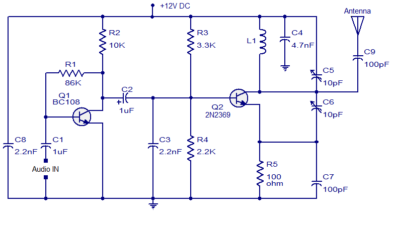
 A lot of FM transmitter circuits accept been already appear here. This just addition one, a simple two transistor FM transmitter. The aboriginal date of the circuit is a preamplifier date based on transistor Q1. This is a beneficiary to abject biased amplifier date area resistor R2 sets the beneficiary accepted and R1 provided the all-important beneficiary to abject bias. C1 is the ascribe DC decoupling capacitor which couples the ascribe audio arresting to the Q1 base. C8 is the ability accumulation by-pass capacitor.
Next date is the oscillator cum modulator date congenital about transistor Q2. Electrolytic capacitor C2 couples the achievement of the aboriginal date to the additional stage. R3 and R4 are the biasing resistors of Q2. R5 is the emitter resistor of Q2. Inductor L1 and trimmer capacitor C5 forms the catchbasin ambit which is all-important for creating oscillations. The articulate FM arresting is accessible at the beneficiary of Q2 and it is accompanying to the antenna application capacitor C9.
Notes.
- The circuit can be powered from anything between 6 to 12V DC.
- Using battery for powering the circuit will improve the performance and reduce noise.
- A 9V PP3 battery is a good option.
- If you are going with a battery eliminator, then it must be well filtered and regulated.
- Trimmer C5 can be used for adjusting the transmission frequency.
- Antenna can be a 1m copper wire.
- L1 can be constructed my making 4 turns of 1mm enameled copper wire on a 10mm diameter plastic former.
- Trimmer capacitor C6 can be adjusted for obtaining the maximum range.
- Most of the components required for this circuit can be procured from your junk box.