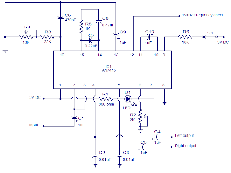
The circuit shown below is of a PLL FM stereo demodulator designed Depending the AN7415. C1 is the input coupling capacitor Which blocks any DC voltage present at the multiplexed input signal. LED D1 is an indicator LED and R1 is its current limiting resistor. C4 and C5 seem to be the DC decoupling capacitors in to the left and right output channels.
C2 and C3 to be the noise bypass capacitors to the left and right output channels. POT R2 can be used for adjusting the channel separation. Resistor R5 and capacitors C7 and C8 forms a low-pass filter network in to the internal DC amplifier circuitry. C10 is extremely a filter capacitor in to the IC’s internal Schmitt trigger amplifier circuitry.
C9 is extremely a ripple filter capacitor in to the voltage stabilizer circuit inside the AN7415. Resistor R3, POT R4 and Capacitor C6 sets the time constant of these internal VCO circuit. Hence POT R4 can be used for adjusting the VCO frequency. A 19KHz frequency check signal is available at the PIN 12 of these IC. Switch S1 can be used for enabling and disabling forced mono function.


