Search Other Blog

Showing posts with label Amplifier. Show all posts

BD5460 class D amplifier IC

BD5460 class D amplifier ICBD5460 is a low power Class D amplifier that can be acclimated in low ability applications like handheld audio devices. BD5460 does not crave an LC clarify at the apostle achievement and can be apprenticed application a battery, The standby accepted of BA5460 is about aught and there is no about-face ON / OFF clicks. The BD5460 can bear 0.8 watts into an 8 ohm apostle at 3.6 V accumulation voltage. The ability accumulation voltage ambit is from 2.5 to 6.5 V DC. The IC has a congenital standby function, abbreviate ambit protection, thermal abeyance and beneath voltage lockout.

Two chic D amplifier circuits application BD5460 are apparent below. The aboriginal one is a cogwheel ascribe chic D amplifier while the additional one is a individual concluded ascribe chic D amplifier. The 0.1uF capacitors (C1, C2, C3 and C4) are ascribe DC decoupling capacitors. The lower cut off abundance of the amplifier depends on these capacitors. 10uF capacitors (C5 and C6) are the ability accumulation filters. S1 and S2 are the abeyance switches. Abutting the C1 pin to the top argumentation will accomplish the IC alive and abutting the C1 pin to arena will put the Ic into abeyance mode.

Notes.

  • The power supply voltage can be between 2.5 to 6.5V DC.
  • For the circuit shown here, the supply voltage must be 3.6 V DC.
  • Powering the circuit from a battery is the better option because it reduces noise.
  • If you are using a DC power supply, then it must be well regulated and filtered.
  • Audio inputs have to be connected with respect to the ground.
READ MORE - BD5460 class D amplifier IC

STK4038 60W Amplifier Circuit

STK4038 60W Amplifier Circuit
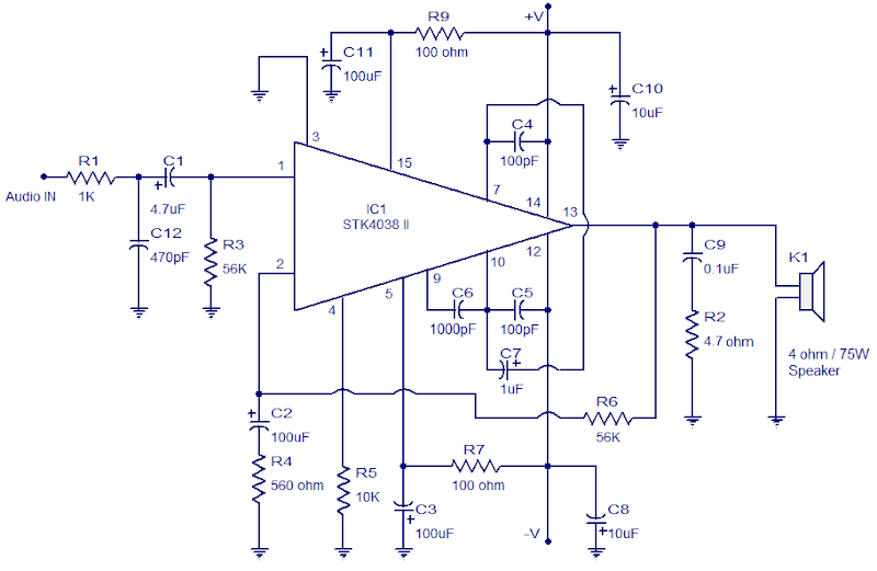
STK4038 is an built in AF power amplifier that will deliver 60 watts of output power into a 4 ohm load. The internal fixed current circuitry reduces switch ON/OFF clicks. The IC supports the addition of external circuits for thermal shutdown, pop noise reduction, output short circuit protection etc.

The 60 watt amplifier is designed Depending about the datasheet and performs incredibly well. Capacitor C1 is the input DC decoupling capacitor Which blocks any DC level present at the audio input and C12 is the input by-pass capacitor. R1 is the input resistor.

C10 and C8 seem like the ripple filter capacitors in to the certain and negative power supply rails. R9 and R7 seem like the current limiting resistors in to the internal driver stage although C11 and C3 seem like their corresponding filter capacitors. Resistor R6 feeds back a portion of those output signal in to the inverting input (pin2). Gain these amplifier depends about the value of R6. C9 and R2 forms a Zobel network Which improves the high frequency stability of those amplifier.
READ MORE - STK4038 60W Amplifier Circuit

BA5406 Stereo Amplifier Circuit

BA5406 Stereo Amplifier Circuit
BA5406{is a monolithic integrated stereo amplifier from ROHM semiconductors. It will deliver 5W per channel into a 4 ohm loudspeaker at 9V supply. Amplifiers based on BA5406 doesn't need an output coupling transformer and can be operated from single supply.

In the circuit diagram, BA5406 is configures to deliver 5×2 watts into 4 ohm loudspeakers at a supply voltage of 9V. Capacitor C3 is a power supply filter capacitor. C11 and C12 are input DC decoupling capacitors for the left and right channels.

C3 and R2 forms a Zobel network for the left output while C6 & R3 forms the same for the correct channel. Purpose of the Zobel network is to cut back oscillations and improve high frequency stability of the amplifier. Potentiometers R5 and R6 serves as the volume control for the left and right channels. CapacitorsC4 and C8 couple the outputs of the amplifier to the speakers. C9 and C10 are noise filtering capacitors. C1 and C5 are bootstrap capacitors for the left and right channels.
READ MORE - BA5406 Stereo Amplifier Circuit

100W Subwoofer Amplifier Circuit

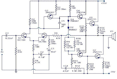
100W Subwoofer Amplifier CircuitThis is the circuit diagram of a fully transistorized subwoofer amplifier that can produce full output 100W.There seven including four in the output stage. Transistors Q1 and Q2 form the pre-amplifier. The transistors Q4 to Q7 as the output stage. Since no integrated circuits used in the circuit is very robust and can be easily mounted on a general purpose PCB.

Notes.

  • The circuit can be powered from a +35V/-35V, 5A dual power supply.
  • Use a 100W, 12 inch sub woofer at the output.
  • All electrolytic capacitors must be rated 100V.
  • The transistor Q4 to Q7 must be fitted with heat sinks.
READ MORE - 100W Subwoofer Amplifier Circuit

TDA2822 Stereo Amplifier circuit

TDA2822 Stereo Amplifier circuit
TDA2822 is a stereo low-power op amplifier used in the Walkman and headphones. It can output 250 milliwatts. TDA2822 is an operational amplifier ideal for low production. It is a good option as a stereo preamplifier circuits high-powered amplifier. It has two inputs and two outputs that can generate 250 milliwatts of output.power. The circuit of the amplifier IC is well established for noise-free operation. The outputs can be coupled directly to the speakers through the decoupling capacitors.
READ MORE - TDA2822 Stereo Amplifier circuit

Simple Class-B amplifier-Opamp TL082

Simple Class-B amplifier-Opamp TL082
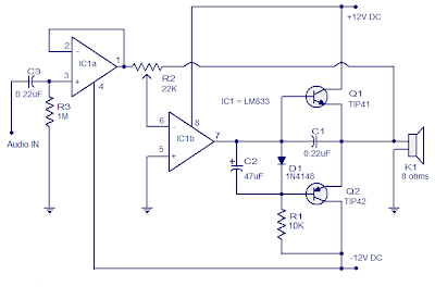
The circuit shown here is of a simple and easy Class-B audio amplifier based on opamp TL082, transistors TIP141 and TIP142. LM833 will be twin opamp with high slew rate and low distortion significantly designed for audio applications. This audio amplifier circuit will deliver 15 watt audio output into an 8 ohm speaker at +12/-12V DC twin supply.

Both opamps within the IC are used here. IC1a is wired as a buffer and capacitor C3 will the task of input DC decoupling. Ic1b is wired within the inverting mode and it provides negative feedback. Complementary power transistors TIP41 and TIP42 are wired within the class B push pull schematic and that they drives the loud speaker. Diode D1 provides 0.7V bias voltage for the push pull combine and capacitor C2 protects the 0.7V bias voltage across D1 from serious voltage swings at the IC1b’s output.

Notes :

  • The audio amplifier circuit must be assembled on a good quality PCB.
  • Use a holder for mounting IC1.
  • Use a +12/-12V dual supply for powering the amplifier.
  • Potentiometer R2 can be used as a volume control.
  • Raising the power supply voltage will increase the output power. Anyway note the following points.
  • TIP42 and 41 can handle only up to 6A.
  • Maximum supply voltage IC1 can handle is +16/-16 V DC.
READ MORE - Simple Class-B amplifier-Opamp TL082