Search Other Blog

Showing posts with label Audio Circuits. Show all posts

LM3900 Multi-channel Audio Mixer

LM3900 Multi-channel Audio MixerA simple multi-channel audio mixer circuit using LM3900 quad amplifier is given below. The circuit consists of 4 channel quad amplifier (LM3900). two mic audio inputs and two direct line inputs are offered in this circuit. By adding constant circuit parallel with this, you'll be able to increase the quantity of inputs according to the applications.

Each input is connected to the inverting terminal of LM3900. The built in amplifier of each section amplifies every audio input separately and is fed to the output terminals. The output terminal from every channel is connected to one output line with a resistance not greater than 680K and produces a mixed audio at the output with terribly low noise. This audio mixer circuit doesn’t use a low impedance input to combine ideal sources. Capacitors C1 to C4 are the decoupling capacitors for the corresponding channels. C5 is the output decoupling capacitor.
READ MORE - LM3900 Multi-channel Audio Mixer

MAX5486 Digital Volume Control

MAX5486 Digital Volume Control
A two channel digital volume control circuit using IC MAX5486 is shown here. MAX5486 can be quite a 40K dual digital volume / balance controller that has a pushbutton interface. The IC has a built in bias voltage source that eliminated the need of an external circuit towards the same purpose and thereby by reduces external parts count.

The IC also comes through an LED status indicator driver circuit that seem to be either employed for driving the status indicator LEDs And this indicates the volume level and balance level. The IC might be operated in one a single or dual power supply and is out there in 24 pin TSSOP package. The volume control circuit Depending on MAX5486 might be applied in a lot applications like personal audio systems, hand held audio devices, home theatre systems, car audio systems, computer audio systems etc.
READ MORE - MAX5486 Digital Volume Control

LA3161 Stereo Preamplifier Circuit

LA3161 Stereo Preamplifier Circuit
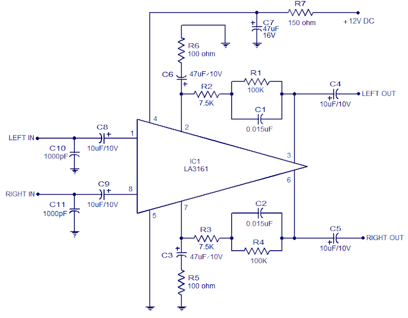
LA3161 is an integrated 2 channel pre-amplifier meant for car stereo applications. The LA3161 contains a built in voltage regulator that plays an excellent role in improving ripple rejection . The IC needs minimum number of external components and the noise level is extremely low. The IC has high input impedance (around 100K) and is available in an 8 pin SIL package.

In the circuit each of the built in amplifier section are used. Capacitors C8 and C9 are input coupling capacitors. Capacitors C3 & C6 are noise filter capacitors. The lower cut-off frequency depends on the value of C3 and C6 network comprising of components R1, R2 & C1 defines the frequency characteristics of left channel and the network consisting of R3, R4 &C2 defines the frequency characteristics of the correct channel. C4 and C5 are output coupling capacitors. C7 is the power supply filter capacitor and it should be connected as close as possible to the power input pin (pin 4) of the IC. This IC doesn’t have short circuit protection, and short between pins may cause damage. C10 and C11 are meant for preventing radio interference, interference from engines etc.
READ MORE - LA3161 Stereo Preamplifier Circuit

BD5460 Class D Amplifier Circuit

BD5460 Class D Amplifier Circuit
BD5460 is a low power {lass D amplifier that can be employed in low power applications like handheld audio devices. BD5460 doesn't need an LC filter at the speaker output and can be driven employing a battery, The standby current of BA5460 is usually zero and there's no switch on / OFF clicks. The BD5460 can deliver 0.8 watts into an 8 ohm speaker at 3.6 V supply voltage. the power supply voltage range is from 2.5 to 6.5 V DC. The IC contains a built-in standby function, short circuit protection, thermal shutdown and below voltage lockout.

Two class D amplifier circuits using BD5460 are shown here. the first one is a differential input class D amplifier while the second one is a single ended input class D amplifier. The 0.1uF capacitors (C1, C2, C3 and C4) are input DC decoupling capacitors. The lower interrupt frequency of the amplifier depends on these capacitors. 10uF capacitors (C5 and C6) are the power supply filters. S1 and S2 are the shutdown switches. Connecting the C1 pin to the high logic can create the IC active and connecting the C1 pin to ground will put the Ic into shutdown mode.
READ MORE - BD5460 Class D Amplifier Circuit

100W MOSFET Power Amplifier based on IRFP240

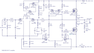
100W MOSFET Power Amplifier based on IRFP240A 100W MOSFET power amplifier circuit based on IRFP240 and IRFP9240 MOSFETs is shown here. The amplifier operates from a +45/-45 V DC twin supply and might deliver 100 watt rms into an 8t ohm speaker and 160 watt rms into a 4 ohm speaker. This Hi-Fi amplifier circuit is appropriate for lots applications like general purpose amplifier, guitar amplifier, keyboard amplifier. The amplifier and also used as a sub woofer amplifier however a subwoofer filter stage should be added before the input stage. The amplifier has a low distortion of 0.1%, a damping issue bigger than 200, input sensitivity of 1.2V and also the bandwidth is from 4Hz to 4 KHz.

Capacitor C8 is the input DC decoupling capacitor that blocks DC voltage if any from the input source. IF unblocked, this DC voltage can alter the bias setting s of the succeeding stages. Resistor R20 limits the input current to Q1 C7 bypasses any high frequency noise from the input. Transistor Q1 and Q2 forms the input differential combine and the constant current source circuit designed around Q9 and Q10 sources 1mA. Preset R1 is employed for adjusting the voltage at the output of the amplifier. Resistors R3 and R2 sets the gain of the amplifier. The second differential stage is created by transistors Q3 and Q6 whiles transistors q4 and Q5 forms a current mirror that makes the second differential combine to empty an identical current. this is worn out order to boost linearity and gain. Power amplification stage based on Q7 and Q8 that operates in thee category AB mode. Preset R8 will be used for adjusting the quiescent current of the amplifier. The network comprising of capacitor C3 and resistor R19 improves high frequency stability and prevents the possibility of oscillation. F1 and F2 are safety fuses.

Set R1 at midpoint before powering up and then change it slowly in order to induce a minimum voltage (less than 50mV0 at the output. Next step is fixing the quiescent current and keep the preset R8 in minimum resistance and connect a multimeter across points marked X & Y in the circuit diagram. currently change R8 so that the multimeter reads 16.5mV that corresponds to 50mA quiescent current.

Notes

  • Assemble the circuit on a good quality PCB.
  • Use a +45/-45 V DC, 3A dual supply for powering the circuit.
  • Power supply voltage must not exceed +55/-55 V DC.
  • Before connecting the speaker, check the zero signal output voltage of the amplifier and in any case it should not be higher than 50mV. If it is higher than 50mV, check the circuit for any error. Replacing Q1, Q2 with another set could also solve the problem.
  • Fit Q7 and Q8 to a 2°C/W heat sink. Both Q7 and Q8 must be isolated from the heat sink using mica sheets. Heat sink mounting kits for almost all power transistors/ MOSFETs of almost all package styles are readily available in the market.
  • All resistors other than R10, R11 and R19 are 1/4 watt metal film resistors. R10 and R11 are 5W wire wound type while R19 is a 3W wire wound type.
READ MORE - 100W MOSFET Power Amplifier based on IRFP240